Our fully realized idea

Left Hand: Y controls both color and note, and the Z controls the type of instrument.
Right Hand: Y controls both form (position of particle system) and note, and the Z controls type of instrument.
However, the problem with this is that we would have two sets of Arduinos utilizing two applications, which was then advised by Danny we would need OSC to communicate both Ableton and TouchDesigner. So Danny advised on separating our gloves to one tool each as show below:

We wanted to still further into the glove/instrument idea, so Rebecca and I decided to do sets of gloves ourselves and came up with this:
We imagine two people, one with the sound and another with the visual set of gloves - and if we further this project to put the ideas together.


Figuring out TouchDesigner


My next steps this next week in TouchDesigner is adding the controller code within the Arduino code and connecting the serial port with two Arduinos.
MIDI in Ableton


For the final project, Rebecca and I want to combine our projects, pitch-manipulating gloves and a micro controlled visualizer, together. We touched therapeutic resolutions to the mind and body in both of our projects.
Somatic experiences
Collectively, we want our goal to be strengthening body awareness. Both a tool for simple interaction and performance, we want our project to have versatility.
Questions to answer:
- Is the interface understandable to the participant with minimal instruction? Do they know what to do by looking at, listening to, or touching the interface?
- Can someone besides you use it?
- Can it be started, stopped, and reset without your intervention
- Make the interaction iterative. In other words, it’s not just one action by the participant, but they read the interface, take action, read the device’s response, and take another action, in a continued loop.
Iterations on iterations
Our initial idea consisted a pair of gloves creating sound, the left hand controlling bass and the right hand controlling a melody. As the melody changes, the visual is manipulated adjacent to the sound.

Rebecca's initial idea for her glove project was "creating a musical instrument that also functions as a paintbrush". This transformed into pitch-tuning gloves creating a Perlin noise bezier curve that was controlled by mouseX and mouseY.
We decided to continue pursuing 'musical gloves', keeping the physicality. And we want to pair it with a visual performance, which could be a brush, manipulating waves, etc.
Potential new sensors
Next Steps
- Challenges includes purchasing another Arduino to create a pair of gloves and learning how to implement Bluetooth LE to avoid problems with long wires.
- Creating a NEW interactive visual utilizing Touch Designer and connecting serialport
- Finalizing the idea of our 'musical instrument' gloves, which hand controls what?
Touch Designer Resources
Cool reads on digital performance live art
Digital interactive art in public space and the effect of public art on the community
The Development of an Audio-Visual Language for Digital Music Performance


Prompt:
A device that allows a person to control media on a personal computer using communication between a microcontroller and the personal computer using asynchronous serial communication.
Project:
Created an atmospheric visualizer and looper to immerse the user in an experimental and curious exploration.

The microcontroller included 4 sliding potentiometers (speed, hue, variation, and volume) and 4 button switches (various synths).
Arduino microcontroller code:
const int buttonPinA = 4;      // digital input
const int buttonPinB = 5;
const int buttonPinC = 6;
const int buttonPinD = 7;

void setup() {
  // configure the serial connection:
  Serial.begin(9600);
  // configure the digital input:
  pinMode(buttonPinA, INPUT);
  pinMode(buttonPinB, INPUT);
  pinMode(buttonPinC, INPUT);
  pinMode(buttonPinD, INPUT);
}

void loop() {
  // slider 1: speed
  int sensorValue = analogRead(A0);
  // print the results:
  Serial.print(sensorValue);
  Serial.print(",");

  // slider 2: hue
  sensorValue = analogRead(A1);
  // print the results:
  Serial.print(sensorValue);
  Serial.print(",");

    // slider: variation
  sensorValue = analogRead(A2);
  // print the results:
  Serial.print(sensorValue);
  Serial.print(",");

    // volune of background music
  sensorValue = analogRead(A3);
  // print the results:
  Serial.print(sensorValue);
  Serial.print(",");

  // read the button:
  sensorValue = digitalRead(buttonPinA);
  // print the results:
  Serial.print(sensorValue);
  Serial.print(",");

  // read the button:
  sensorValue = digitalRead(buttonPinB);
  // print the results:
  Serial.print(sensorValue);
  Serial.print(",");

  // read the button:
  sensorValue = digitalRead(buttonPinC);
  // print the results:
  Serial.print(sensorValue);
  Serial.print(",");

  // read the button:
  sensorValue = digitalRead(buttonPinD);
  // print the results:
  Serial.println(sensorValue);

  delay(500);
}
Visualizer code:
I took this open source Code Pen and added serial port to connect with the microcontroller code. Link to full code
I then projected it onto seamless paper with a projector, hdmi cable, and speakers to scale the experience.

November 9, 2020 — No Comments
I2C and SPI Lab (Class 8), Duplex Serial Comm Lab (with Built-in IMU this time) (Class 7)
I2C Communication With a Color, Gesture, and Proximity sensor


Notes:
- I2C is a common protocol among many ICs, and it’s handy because you can combine many devices on the same bus.
- I2C devices exchange bits of data whenever the shared clock signal changes.
SPI Communication With A Digital Potentiometer
Two-way (Duplex) Serial Communication using an Arduino and Processing

Program the Microcontroller to Read the IMU:
#include <Arduino_LSM6DS3.h>

void setup() {
  Serial.begin(9600);
  while (!Serial) {
    ; // wait for serial port to connect. Needed for native USB port only
  }
  if (!IMU.begin()) {
    Serial.println("Failed to initialize IMU!");
    while (true); // halt program
  }
  Serial.println("IMU initialized!");
}
void loop() {
  float aX, aY, aZ;
  float gX, gY, gZ;
  const char * spacer = ", ";

  if (
    IMU.accelerationAvailable()
    && IMU.gyroscopeAvailable()
  ) {
    IMU.readAcceleration(aX, aY, aZ);
    IMU.readGyroscope(gX, gY, gZ);
    Serial.print(aX); Serial.print(spacer);
    Serial.print(aY); Serial.print(spacer);
    Serial.print(aZ); Serial.print(spacer);
    Serial.print(gX); Serial.print(spacer);
    Serial.print(gY); Serial.print(spacer);
    Serial.println(gZ);
    delay(1000);
  }
}
Add Serial Handshaking:
void loop() {
  // values for acceleration and rotation:
  float xAcc, yAcc, zAcc;
  float xGyro, yGyro, zGyro;

  // check if the IMU is ready to read:
  if (IMU.accelerationAvailable() & amp; & amp;
      IMU.gyroscopeAvailable()) {
    // read accelerometer and gyrometer:
    IMU.readAcceleration(xAcc, yAcc, zAcc);
    IMU.readGyroscope(xGyro, yGyro, zGyro);

    // update the filter, which computes orientation:
    filter.updateIMU(xGyro, yGyro, zGyro, xAcc, yAcc, zAcc);

    // print the heading, pitch and roll
    roll = filter.getRoll();
    pitch = filter.getPitch();
    heading = filter.getYaw();
  }

  // if you get a byte in the serial port,
  // send the latest heading, pitch, and roll:
  if (Serial.available()) {
    char input = Serial.read();
    Serial.print(heading);
    Serial.print(",");
    Serial.print(pitch);
    Serial.print(",");
    Serial.println(roll);
  }
}
Arduino Code (with serial port .js) :
var serial;          // variable to hold an instance of the serialport library
var portName = 'COM3'; // fill in your serial port name here

var portSelector; // a select menu for the port list
// orientation variables:
let heading = 0.0;
let pitch = 0.0;
let roll = 0.0;

function setup() {
  createCanvas(500, 600, WEBGL);
  smooth();                        // antialias drawing lines
  serial = new p5.SerialPort();    // make a new instance of the serialport library
  serial.on('list', printList);    // set a callback function for the serialport list event
  serial.on('connected', serverConnected); // callback for connecting to the server
  serial.on('open', portOpen);     // callback for the port opening
  serial.on('data', serialEvent);  // callback for when new data arrives
  serial.on('error', serialError); // callback for errors
  serial.on('close', portClose);   // callback for the port closing

  serial.list();                   // list the serial ports
}

// get the list of ports:
function printList(portList) {
  // make a select menu and position it:
  portSelector = createSelect();
  portSelector.position(10,10);

  // portList is an array of serial port names
  for (var i = 0; i < portList.length; i++) {
    // Display the list the console:
    // console.log(i + " " + portList[i]);
    // add item to the select menu:
    portSelector.option(portList[i]);
  }
  // set a handler for when a port is selected from the menu:
  portSelector.changed(openPort);
}

function openPort() {
  var thisPort = portSelector.value();
  if (thisPort != null) {
    serial.open(thisPort);
  }
}

function serverConnected() {
  print('connected to server.');
}

function portOpen() {
  print('the serial port opened.')
  // send a byte to prompt the microcontroller to send:
  serial.write('x');
}

function serialError(err) {
  print('Something went wrong with the serial port. ' + err);
}

function portClose() {
  print('The serial port closed.');
}

// callback function for incoming serial data:
function serialEvent() {
   // read from port until new line:
   let message = serial.readStringUntil('\n');
   if (message != null) {
      let list = split(trim(message), ',');
      if (list.length >= 3) {
         // conver list items to floats:
         heading = float(list[0]);
         pitch = float(list[1]);
         roll = float(list[2]);
         console.log(heading + ',' + pitch + ',' + roll);
         // send a byte to the microcontroller to get new data:
         serial.write('x');
      }
   }
}

// draws the Arduino Nano:
function drawArduino() {
   // the base board:
   stroke(0, 90, 90); // set outline color to darker teal
   fill(0, 130, 130); // set fill color to lighter teal
   box(300, 10, 120); // draw Arduino board base shape

   // the CPU:
   stroke(0);         // set outline color to black
   fill(80);          // set fill color to dark grey
   translate(30, -6, 0); // move to correct position
   box(60, 0, 60);    // draw box

   // the radio module:
   stroke(80);       // set outline color to grey
   fill(180);        // set fill color to light grey
   translate(80, 0, 0); // move to correct position
   box(60, 15, 60);  // draw box

   // the USB connector:
   translate(-245, 0, 0); // move to correct position
   box(35, 15, 40);   // draw box
}

function draw() {
   // update the drawing:
   background(255); // set background to white
   push();          // begin object to draw

   // variables for matrix translation:
   let c1 = cos(radians(roll));
   let s1 = sin(radians(roll));
   let c2 = cos(radians(pitch));
   let s2 = sin(radians(pitch));
   let c3 = cos(radians(heading));
   let s3 = sin(radians(heading));
   applyMatrix(c2 * c3, s1 * s3 + c1 * c3 * s2,
      c3 * s1 * s2 - c1 * s3, 0, -s2, c1 * c2,
      c2 * s1, 0, c2 * s3, c1 * s2 * s3 - c3 * s1,
      c1 * c3 + s1 * s2 * s3, 0, 0, 0, 0, 1);

   // draw arduino board:
   drawArduino();
   pop(); // end of object
}

I2C and SPI Lab
I could not participate in this week's I2C and SPI communication lab as my parts did not come in on time. Will be following this lab next week.
Project 2 Update:

My next steps included creating the interactive visual aid for my visualizer. I initially started coding with p5 Pixel Arrays but found that it was extremely limiting.

So I looked for more possibilities that were interactive visuals and moving gradients (or anything similar) and found this CodePen with an already interactive interface.
I have been playing around with this code and tweaking the parameters to make it easier when I use SerialEvent() and the potentiometers.

https://editor.p5js.org/natayie/present/Xvan9mbj-
Purchased extra parts for the housing:

October 28, 2020 — No Comments
Two-Way (Duplex) Serial Communication Using An Arduino and P5.js (Class 7)
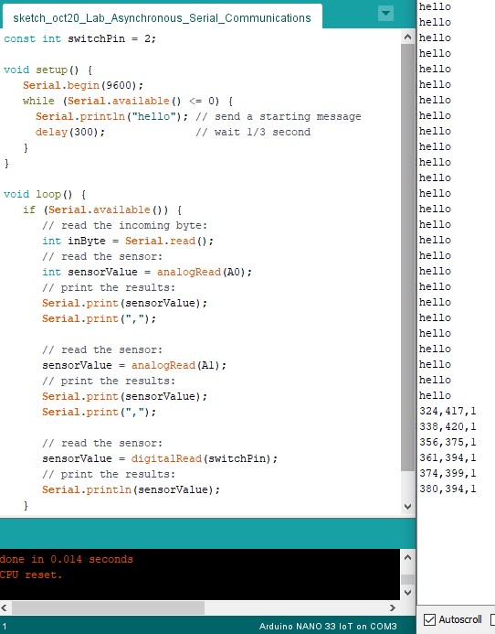
Goal: Send data from multiple sensors to a program in P5.js. Use the data from the sensors to create a pointing-and-selecting device (i.e. a mouse).
For my set up, I used two potentiometers and a pushbutton for my two analog sensors and switch. Meaning, my ranges should come out to 0-1024 for the potentiometers and 0-1 for the switch.

Receiving data in p5.js

Initially, the program did not work, so I inserted console.log() to run and see if serialEvent was firing. I realized with the UI of the program, I have to click COM3 even though it was already selected to start the program.
When it ran, I noticed my values were extremely high, throwing the ellipse off the grid. I changed the map() values to fit the potentiometers since the original code in the lab were fitted for the accelerometers.
Creating another interface (Project 2)
Music player that is also a sound visualizer.
A 'mood machine' that asks the user a variety of questions to customize a visual/audio experience (gradient animation on p5). Along with this, there are loaded up songs in p5 that can be played with a the UI of a music player.
I got visual inspiration from the scene/room in the mini-series on Netflix called "Maniac", where they store their patients while they are experiencing their drug-induced test. The atmospheric light from above the patients and the colorful, crazy LED buttons led me to create a machine that can affect mood or the atmosphere, like a 'weather machine'.


Sketch of user interface:


Instead of having deliberate instructions of what each of the switches and sliders (sliding potentiometers) do, I want the buttons to have a more vague context around them surrounding the idea of the user's mood. I will research more on determining wellness through surveys and models of other wellness applications.
I hope to finish this project with a housing of the physical interface and have the screen be projected on through a projector to scale the effect of the 'atmosphere'. My final project may include LED string lights and clouds to reign the 'weather' theme.
Next Steps:
- Code p5 program of interactive visual aid
- Code p5 music player and choose various songs
- Write Arduino code for microcontroller
Serial Communication
Connecting the sensors:
- Two analog inputs (accelerometer built-in on the Arduino Nano 33 IoT + pushbutton)
- One digital input

My switchPin kept giving me "1" as an output and could not figure out the reason for it.
Serial Input

At first, putting all the files together came at an ease, then I struck a problem with my serial port not connecting and the sensor values not moving. I realized I did not have the serialcontrol app not open.


Serial Output
My initial idea... was much harder than I thought I could handle... But I'm glad that I pushed my idea farther than my current skillset to really challenge my thinking on creating an idea combined of a keyboard and combination lock.
Initial Idea: Sing-along game: The speaker will play 3-4 notes (C, A, B, G) and the player will have to repeat what is played. The LED light will turn start off with red, and then the LED light will turn green if the tune is played correctly.
My first challenge was just getting the switch buttons to play individually. I made the mistake to start off with having the switches be in a parallel, when they should all be treated separately.
Then when I finally had all the buttons on the board, each button would play including the button before it, then I readjusted the wiring to be much more simpler.


Creating the housing was definitely my favorite part. I had an idea of a mat where I hit each one with a mallet. Then realized as I was creating my circuit that I would need an individual mallet for each note, which wasn't in my scope for this project. I then just continued with the idea for a pop-up buttons for time's sake. I chose colors that matched the buttons and blobby shapes to keep it super playful! I then replaced the switch buttons with wires and connected them with foil. The letters on the buttons represent the note.
Combining the combination lock idea to recreate "Simon Says"
I realized as I created const int variables with words versus numbers, I did not do myself a favor as creating combination locks requires a for loop using numbers.
What I learned/got better at understanding:
- if/else statements and not needing switchState
- utilizing int ___[] = {___, ___, ___ } and how these start at 0!!!
- Learned about more complicated if statements, creating own voids, and utilizing for loops to make combination locks and patterns.